The projected building must be equipped with fire warning devices of type 2.
To notify people about the fire, sirens of the "Mayak-12-3M" type (LLC "Elektrotekhnika i Avtomatika", Russia, Omsk) and light sirens "TS-2 SVT1048.11.110" (display board "Exit") will be used. S2000-4 (CJSC NVP "Bolid").
Fire-resistant cable KPSEng (A) -FRLS-1x2x0.5 is used for the fire warning network.
For email power supply of equipment at voltage U = 12 V, a redundant power supply is used. power supply "RIP-12" isp.01 with a storage battery cap. 7 Ah. Rechargeable batteries email source power supplies ensure the operation of the equipment for at least 24 hours in standby mode and 1 hour in the "Fire" mode when the main power source is disconnected.
Basic requirements for SOUE are set out in NPB 104-03 "Warning and evacuation systems for people in case of fires in buildings and structures":
3. Design assumptions made
Based on the geometric dimensions of the premises, all premises are divided into only three types:
- "Corridor" - the length is 2 or more times the width;
- "Hall" - an area of over 40 sq. M. (not applicable in this calculation).
Place one siren in a room of the "Room" type.
4. Table of sound attenuation values
In air, sound waves are attenuated due to air viscosity and molecular attenuation. The sound pressure decreases in proportion to the logarithm of the distance (R) from the siren: F (R) = 20 lg (1 / R). Figure 1 shows a graph of sound pressure attenuation versus distance from the sound source F (R) = 20 lg (1 / R).

Rice. 1 - Graph of attenuation of sound pressure depending on the distance to the sound source F (R) = 20 lg (1 / R)
To simplify the calculations, below is a table of the actual values of the sound pressure levels from the Mayak-12-3M siren at various distances.
Table - Sound pressure generated by a single siren when it is switched on at 12V at different distances from the siren.
5. Selecting the number of sirens in a specific type of premises
The floor plans show the geometrical dimensions and area of each room.
In accordance with the previously accepted assumption, we divide them into two types:
- "Room" - area up to 40 sq. M;
- “Corridor” - the length is 2 or more times the width.
- fireproof -30 dB (A);
- standard -20 dB (A)
- H under. - height of the siren from the floor;
- 1.5 m - level 1.5 meters from the floor, at this level is the sound plane;
- h1 - excess over the level of 1.5 m to the suspension point;
- W is the width of the room;
- D - the length of the room;
- R is the distance from the siren to the "calculated point";
- L - projection R (distance from the siren to the level of 1.5 m on the opposite wall);
- S - scoring area.
- D - the length of the room, in accordance with the plan, is 6.055 m;
- W - the width of the room, in accordance with the plan, is 2.435 m;
- If the siren will be placed above 2.3 m, then instead of 0.8 m, you need to take the h1 dimension that exceeds the suspension height above the level of 1.5 m.
- Pdb is the sound pressure of the loudspeaker, according to those. information to the Mayak-12-3M siren is 105 dB;
- F (R) - the dependence of the sound pressure on the distance, equal to -15.8 dB in accordance with Fig. 1 when R = 6.22 m.
- D - the length of the corridor, in accordance with the plan, is equal to 26.78 m;
- Ш - the width of the corridor, according to the plan, is 2.435 m.
- Pdb is the sound pressure of the loudspeaker, according to those. information to the Mayak-12-3M siren is 105 dB;
- F (R) - the dependence of the sound pressure on the distance, equal to -14.8 dB in accordance with Fig. 1 when R = 5.5 m.
- N - permissible constant noise sound level, for dormitories is 75 dB;
- ЗД - sound pressure margin equal to 15 dB.
It is allowed to place one siren in a room of the "Room" type.
In a room of the "Corridor" type - several sirens will be placed, evenly spaced throughout the room.
As a result, the number of sirens in a particular room is determined.
The choice of the "calculated point" - a point on the sounding plane in a given room, as far as possible from the siren, in which it is necessary to ensure the sound level is at least 15 dBA higher than the permissible constant noise sound level.
As a result, the length of the straight line connecting the point of attachment of the siren with the "calculated point" is determined.
Design point - a point on the sounding plane in a given room, as far as possible from the siren, in which it is necessary to ensure a sound level at least 15 dBA higher than the permissible constant noise sound level, in accordance with NPB 104-03, clause 3.15.
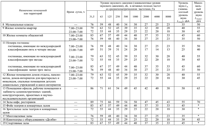
Based on SNIP 23-03-2003, clause 6 "Norms of permissible noise" and "Table 1" given in the same place, we deduce the values of the permissible noise level for the hostel of working specialists equal to 60 dB.
The calculations should take into account the attenuation of the signal when passing through the doors:
Symbols
We will accept the following conventions:
5.1 Calculation for a room of the "Room" type
Let's define the "calculated point" - the point that is maximally distant from the siren.
For suspension, select "smaller" walls, opposing along the length of the room, in accordance with NPB 104-03 in clause 3.17.
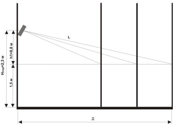
Rice. 2 - Vertical projection of the wall sounder fixing on the airbag
Place the siren in the middle of the "Room" - in the center of the short side, as shown in Fig. 3
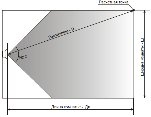
Rice. 3 - Location of the siren in the middle of the "Room"
In order to calculate the size R, it is necessary to apply the Pythagorean theorem:
5.1.1 Determine the sound pressure level at the design point:
P = Rdb + F (R) = 105 + (- 15.8) = 89.2 (dB)
5.1.2 Determine the value of sound pressure, in accordance with NPB 104-03 clause 3.15:
5.1.3 Checking the correctness of the calculation:
P = 89.2> P r.t. = 75 (the condition is met)
SOUE in the protected area.
5.2 Calculation for a room of the "Corridor" type
The annunciators are placed on one corridor wall at intervals of 4 widths. The first are placed at a distance of width from the entrance. The total number of sounders is calculated by the formula:
N = 1 + (L - 2 * W) / 3 * W = 1+ (26.78-2 * 2.435) / 3 * 2.435 = 4 (pcs.)
The quantity is rounded up to the nearest whole number. The placement of sirens is shown in Fig. 4.
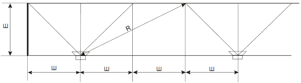
Fig. 4 - Placement of sirens in a room of the "Corridor" type with a width of less than 3 meters and a distance "to the calculated point"
5.2.1 Determine the design points:
"Design point" is located on the opposite wall at a distance of two widths from the axis of the siren ".
5.2.2 Determine the sound pressure level at the design point:
P = Rdb + F (R) = 105 + (- 14.8) = 90.2 (dB)
5.2.3 Determine the value of sound pressure, in accordance with NPB 104-03 clause 3.15:
R r.t. = N + ZD = 60 + 15 = 75 (dB)
5.2.4 Checking the correctness of the calculation:
P = 90.2> P p.t = 75 (the condition is met)
Thus, as a result of calculations, the selected type of Mayak-12-3M siren provides and exceeds the sound pressure value, thereby ensuring clear audibility of sound signals SOUE in the protected area.
In accordance with the calculation, we will carry out the placement of sound annunciators, see Fig. 5.

Fig. 5 - Layout of sirens at elev. 0.000
The end of summer is the hottest time for vacations. You walk along the main street of the seaside town - there are many cafes, restaurants, shops around to the delight of vacationers. Most of them, from the point of view of the organization of warning systems, relate to small and medium-sized objects (if the institution is not located in any shopping and entertainment center of a very impressive size). SECs are usually equipped according to all the rules, including the notorious joint venture 3.13130.2009, and with the notification there everything is more or less clear - specialized systems are used in combination with 100-volt lines and loudspeakers. Small objects are not so simple
Roman Mishin
Technical Director of Schneider Intercom
Usually, the owners of even the smallest establishments have at their disposal some kind of sound reproducing device, the main purpose of which is to create a pleasant sound atmosphere in the room. A little less often, audio equipment is also used to attract the attention of passers-by. The question is, can such devices be used to alert and inform visitors, including in emergency situations?
Complexity of simple systems
It seems that at first glance, there are no obstacles to the use of audio equipment for safety purposes - there would only be a possibility to connect a microphone and an input for connecting a source of external audio signals. But only at first glance it is all so easy.
The first problem is the limited applicability due to the fact that almost all such systems, until recently, were not equipped with devices for ensuring automatic activation in the event of an alarm event and it is simply impossible to certify an audio system as an SOUE according to the requirements of GOST R 53325. small shops or other premises for which the introduction of such systems is generally not necessary. Nevertheless, many owners of small establishments use low impedance audio systems not only for broadcasting music, but also for placing announcements.
Move on. Suppose a low-impedance system or an amplifier still has all the necessary means for using them as warning devices (although such devices are still few in number on the market). As a rule, these are small audio systems, and in the overwhelming majority of cases the number of loudspeakers in them is limited to a few units. But in itself, a small number of speakers cannot be an obstacle. The problem lies elsewhere: with a low-impedance connection, the signal in the loudspeaker line, of course, can reach very significant instantaneous voltage values, but the average value of this parameter is very, very small. As a result, good shielding is required to attenuate external electrical interference, otherwise, with a line length of more than 1 5 m and the presence of a nearby power cables or electrical equipment the sound will become noticeably worse. But that's not all.
As you know, losses in a line with a non-zero resistance are inversely proportional to the voltage in it. Thus, at low voltage, a strong attenuation of the useful signal is inevitable, even at a short distance from the source to the consumer. To reduce losses, it is necessary either to reduce this distance, or to reduce the resistance by increasing the cross-section of the wires supplying the loudspeaker.
Both methods impose severe restrictions on the use of conventional audio systems for broadcast and publicity purposes. As an illustration, we present a method for calculating the minimum cable cross-section for connecting loudspeakers in audio systems.
How to calculate cable cross-section
For the warning system, the calculation of the cable cross-section of the line at a given length is carried out for a given permissible voltage drop in the line (ipad) to the following parameters:
- line voltage - U;
- line length - L;
- power consumption - R.
Voltage drop:
where I is the current in the line.
where is the specific resistance of the material (for copper - 0.0175 Ohm-mm2 / m):
From here we find an expression for calculating the cable cross-section:
In the case when it is necessary to calculate the maximum length of the line, knowing the cross-section of the cable used and the specified voltage drop, the following formula is applied:
It is clearly seen from the above formulas: the higher the voltage in the line, the smaller the cable cross-section is required to create a line of a certain length and the longer the warning line can be organized with a known cable cross-section.
Limitations of low voltage systems
It would seem that everything is clear: the limit for the use of low-voltage systems is small objects with an area of several tens of square meters. However, low-voltage systems have another drawback that further limits the scope of their use. They, with rare exceptions, do not have the ability to monitor the health of the line, and even more so a separate speaker. The lack of such an opportunity is not a desire to reduce the cost of equipment, but a fundamental feature.
All modern control methods use, to one degree or another, the transmission of a special signal through the loudspeaker line during broadcast. In a low-voltage circuit, such a signal - comparable to the amplitude of the wanted signal - can cause sensitive unwanted effects. And why this opportunity, because low-voltage audio systems, as a rule, are equipped with low-impedance speakers, and they must be connected correctly, taking into account that the resistance of the output stage of the power amplifier is equal to the resistance of one speaker system. Under these circumstances, many loudspeakers cannot be connected, no matter how hard you try.
Taking into account the features of low-voltage systems described above, we will explain why it is undesirable to use them as broadcasting devices even for very small establishments and why recently there have been broadcasting systems specially designed for small and medium-sized facilities.
Typical Approach
Since even a small shop or coffee shop has at least two acoustically separated zones (customer and technological), one loudspeaker is not enough.
Sometimes they get out of the situation as follows: one speaker of the stereo system is placed in the client area - the other in the technological one. Of course, this is not entirely correct, because, firstly, the sound of stereo programs is very distorted, and secondly, if you are in one of the zones, it is not always clear (in the absence of line control) whether the speaker works in another the room. In addition, 10 m for a low-voltage system is a distance that can greatly spoil the quality of reproduction and speech intelligibility. The latter circumstance at a decisive moment can be costly for the owner of the establishment.
Special solutions for small objects
Thanks to the development of technology and a culture of doing business in advanced countries, inexpensive broadcast systems have appeared on the Russian market, specially designed for small and medium-sized facilities. They allow you to equip an institution with more than two speakers, create a uniform comfortable sound field and comply with the requirements of the standards for loudness and intelligibility of announcements.

To minimize spatial distortion in such systems, only mono sound is used, and to reduce signal losses, high-voltage warning lines with transformer powered loudspeakers are used. Such equipment has the ability to functionally control the loudspeaker lines and the main elements of the system, but the depth of this control depends on the class of the system and the capabilities of the manufacturer.
1. For small systems, as a rule, they are limited only to control of the amplifier and unbranched warning lines.
2. Nowadays, a method is often used, in which it is possible to constantly monitor the line by periodically passing a special signal - the so-called pilotton, inaudible for the users of the system, followed by measuring the difference in signal strength. If a certain threshold value of this difference is exceeded, a line failure signal is issued. This method has proved to be very simple and reliable and is adopted by most manufacturers of broadcasting equipment.
3. Higher rank systems have monitoring tools that track faults down to the individual speaker. Of course, this requires not only the resources of the central equipment, but also the installation of special modules that monitor the line branch and a separate loudspeaker. Since both individual branches, and even more so the speakers are included in the main line in parallel, if one of the branches or a separate loudspeaker fails, the conditions for the signal passing along the main line will change little and a simple control system for changing the total line resistance or signal attenuation will simply not work. There is a need to equip with additional control modules.
In addition to the sharp rise in the cost of such a system, the costs of installation and configuration increase. It will take more high qualification installation and maintenance personnel And finally, the most important thing is that with an increase in the number of system elements, the likelihood of a malfunction increases. Therefore, control modules installed in line must have the highest reliability, which undoubtedly affects the price. Nevertheless, it is impossible to completely exclude the occurrence of a failure due to the fault of elements of supervision and control.
Next generation alert
More recently, new architecture systems have emerged on the market as a result of advances in audio technology. They allow you to build relatively cheap distributed notification systems of the scale of a shopping and entertainment center, campus, street or even a small one. settlement... In addition, it is possible, without violating the integrity, to split such a system into a set of logically independent small ones.
The essence of the new approach is as follows: from the central controller of the system, digital signal transmission lines are laid, and both audio and signaling and control commands are transmitted over only two wires or network IP infrastructure. The subscribers of the system are both call stations and amplifiers that have full functional control capabilities. Naturally, subscribers can work both together and absolutely independently, thanks to the logical division of segments such a system... This means that in normal mode, each of these segments can broadcast its own music or announcements, and in the event of a general emergency, all devices can receive a signal from the main operator or from the regional warning system. Since each segment contains only subscriber equipment (call station, amplifiers and loudspeakers), owners of small establishments can be relieved of the need to buy their own system - now it is possible to use common system as a subscriber service, like half-forgotten radio hotspots. At the same time, in the normal mode, each institution (subscriber zone) broadcasts its own music and announcements.
As they say, the new is the well-forgotten old, and the technology that was once created for the radio broadcasting network of loudspeakers, taking into account the modern development, opens up new opportunities for business.
Fire-resistant cable for fire alarm systems and warning systems SOUE
Fire-resistant cable (fireproof, fire-resistant) for fire and security and fire alarm systems (OPS) and fire warning and evacuation control systems (SOUE).
Fire resistance of cable(English (grade of) fire resistance) - the ability of the cable to remain operational when exposed to (and after exposure to) an open flame for a specified time and is determined by parameters such as time fire resistance cable (fire resistance limit), open flame temperature, operating voltage, cable laying conditions, etc.Fire resistance of the cable- time determined from the beginning cable fire tests before the appearance of one of the signs in which it loses its performance: short circuit, etc.
A new federal law came into force in May 2009: Federal Law Russian Federation dated July 22, 2008 N 123-FZ "Technical regulations on the requirements fire safety ", describing new requirements for fire safety systems of facilities. Together with the law, some regulations regulating the use of various types of cables in fire safety systems of facilities. The material below can be used as a justification for the use of fire resistant cables in systems fire alarm and warning systems and evacuation management.
Excerpt from the Federal Law of the Russian Federation of July 22, 2008 N 123-FZ "Technical regulations on fire safety requirements"
Article 82. Fire safety requirements for electrical installations of buildings, structures and structures.2. Systems cables and wires fire protection
, means of ensuring the activities of divisions fire department, fire detection systems, warning and evacuation control in case of fire, emergency lighting on escape routes, emergency ventilation and smoke protection, automatic fire extinguishing, internal fire-fighting water supply, elevators for transporting fire protection units in buildings, structures and structures must remain operational in a fire during the time required for the complete evacuation of people to a safe area.
7. Horizontal and vertical channels for laying electrical cables and wires in buildings, structures and structures must be protected from the spread of fire. In places where cable channels, ducts, cables and wires pass through building structures with a standardized fire resistance limit, cable penetrations with a fire resistance limit not lower than the fire resistance limit of these structures must be provided.
8. Cables laid openly must be flame retardant.
2. Communication lines between technical means automatic fire alarm installations must be performed taking into account the provision of their functioning in case of a fire during the time required to detect a fire, to issue evacuation signals, during the time required to evacuate people, as well as the time required to control other technical means.
Article 84.Fire safety requirements to systems for alerting people about fire and managing the evacuation of people in buildings, structures and structures.7. Systems for warning people about a fire and evacuation management must function for the time required to complete the evacuation of people from a building, structure, structure.
Article 143. Fire safety requirements for electrical equipment.
4. Electrical equipment fire protection systems must remain operational in a fire during the time required for the complete evacuation of people to a safe place.
Full text " Technical Regulations on fire safety requirements "
Excerpt from the Code of Rules SP 5.13130.2009. Fire protection systems. Automatic fire alarm and extinguishing installations. Design standards and rules:
13.15 Fire alarm loops. System connecting and supply linesfire automatics.13.15.3 Selection of electrical wires and cables, the methods of their laying for the organization of loops and connecting lines of the fire alarm must be carried out in accordance with the requirements of GOST R 53315, GOST R 53325, the requirements of this section and technical documentation for devices and equipment of the fire alarm system.
13.15.4 Electric wire fire alarm loops and connecting lines should be made with independent wires and cables with copper conductors. Electrical wired fire alarm loops, as a rule, should be carried out with communication wires if technical documentation fire control devices are not provided for the use of special types of wires or cables.
13.15.5 It is allowed to use dedicated communication lines in the absence of automatic control of fire protection means.
13.15.7. Fire resistance wires and cables connected to various components of fire automation systems should be no less than the time these components perform tasks for a specific installation site. The fire resistance of wires and cables is ensured by the choice of their type, as well as the methods of their laying.
13.15.8 In cases where system fire alarm not intended for control of automatic fire extinguishing installations, warning systems, smoke removal and other engineering systems fire safety of the facility, to connect the radial type fire alarm loops with a voltage of up to 60 V to the receiving and control devices, connecting lines can be used, performed by telephone cables with copper conductors of the complex communication network of the facility, provided that communication channels are allocated. In this case, the allocated free pairs from the cross-section to the junction boxes used for the installation of fire alarm loops, as a rule, should be placed in groups within each junction box and marked with red paint.
13.15.12 The diameter of copper conductors of wires and cables must be determined based on the allowable voltage drop, but not less than 0.5 mm.
Full text of SP 5.13130.2009
Excerpt from the Code of Rules JV SP 6.13130.2009 Fire protection systems. Electrical equipment. Fire safety requirements
Article 4. Fire safety requirements.4.1 The cable lines of fire protection systems should be carried out with fire-resistant cables with copper conductors that do not propagate combustion during group laying according to category A in accordance with GOST R IEC 60332-3-22 with low smoke and gas emission (ng-LSFR) or halogen-free (ng- HFFR).
4.5 Cable lines fire protection systems must remain operational in a fire during the time required for the functioning of specific systems of the protected object.
4.6 The cable lines of the warning and evacuation control systems (SOUE) and fire alarm systems involved in ensuring the evacuation of people in case of fire must remain operational in a fire during the time necessary for the complete evacuation of people to a safe area.
4.15 The time for maintaining the operability of cable lines and electrical panels is determined in accordance with GOST R 53316.
| As can be seen from these extracts, there are some contradictions in the requirements of the Technical Regulations and the Code of Practice. For example, pp. 13.15.5 and 13.15.8 of the Code of Rules 5 allow the use of ordinary telephone communication cables for the fire alarm system, if the fire alarm system is not involved in other fire protection systems - SOUE, fire extinguishing, etc. However, paragraph 2 of Art. 103 FZ-123 requires the fire alarm system to work all the time until people are evacuated, i.e. must work during a fire, therefore, be fire resistant. The following logic is traced: The first fire detector sends a signal and fire to the control panel. The following fire alarm loops will transfer the fault to the device, because cables (common) by that time burned out. Why use fire resistant cables for fire alarm systems? The fact is that cables from other fire alarm loops, as a rule, pass along the same cable routes. In this case, the primary information about the operation of one fire detector (s) is not enough. To make a decision on evacuation, it is necessary to understand where the fire is located and in which direction the fire is spreading. This can be reliably judged by the rest of the fire alarm loops only if the cables and cable routes of the fire alarm remain in working order. It is logical to assume that fire authorities, when agreeing on new projects for fire protection of buildings, will require compliance with more stringent requirements for cable lines, i.e. installation of fire-resistant cables. According to clause 13.15.3 of SP 5 and clause 4.1 of SP 6, cables must comply with the requirements of GOST R 53315 and GOST R IEC 60332-3-22: |
Extract from GOST R 53315-2009. Cable products. Fire safety requirements:
6. Preferential areas of application of cable products taking into account their type of performance. V regulatory documents for the cable product, the scope of its application must be indicated, taking into account the indicators fire hazard and type of execution in accordance with table. 2.
| Type of cable product | Fire hazard class1) |
Primary field of application |
| Without execution | O1.8.2.3.4 |
For single installation in cable structures and industrial premises... With group laying - the mandatory use of passive fire protection |
| Executions - ng, ng (A), ng (A F / R), ng (B), ng (C) and ng (D) | A1.8.2.3.4 A2.8.2.3.4 A3.8.2.3.4 A4.8.2.3.4 |
For group laying, taking into account the volume of combustible load in cable structures, outdoor (open) electrical installations (cable racks, galleries). Application in cable rooms is not allowed industrial enterprises, residential and public buildings |
| Execution ng-LS | A1.8.2.2.2 A2.8.2.2.2 |
For group laying, taking into account the volume of combustible load in cable structures and rooms of internal electrical installations, including in residential and public buildings |
| Execution - ng-HF | A1.8.1.2.1 A2.8.1.2.1 A3.8.1.2.1 A4.8.1.2.1 |
For group laying, taking into account the volume of the combustible load in rooms equipped with computer and microprocessor technology; in buildings and structures with a massive presence of people |
| Execution - ng-FRLS | A1.1.2.2.2 A2.1.2.2.2 |
For single or group laying (taking into account the volume of combustible load) of power supply circuits of electrical receivers of fire protection systems, operating rooms and resuscitation and anesthetic equipment of hospitals and hospitals, as well as other electrical receivers that must remain operational in a fire |
| Execution - ng-FRHF | A1.1.1.2.1 A2.1.1.2.1 A3.1.1.2.1 A4.1.1.2.1 | |
| Execution - ng-LSLTx | A1.8.2.1.2 A2.8.2.1.2 |
For single or group laying (taking into account the volume of combustible load) in the buildings of preschool educational institutions, specialized homes for the elderly and disabled, hospitals, dormitories of residential educational institutions and children's institutions |
| Execution - ng-HFLTx | A1.8.1.1.1 A2.8.1.1.1 A3.8.1.1.1 A4.8.1.1.1 | |
| 1) Class of fire hazard of cable products with the lowest indicators of fire hazard. It is allowed to use cable products with higher fire hazard indicators. | ||
According to this GOST, cables with such indices and fire hazard classes must comply with the requirements of the following standards:
GOST R IEC 60331-23-2003 Tests of electrical and optical cables under fire conditions. Maintaining performance. Part 23. Testing and requirements for them. Electric cables for data transmission.
GOST R IEC 60332-3-22-2005 Tests of electrical and optical cables under fire conditions. Part 3-22. Flame spreading along vertically arranged bundles of wires or cables. Category A.
GOST R IEC 60754-1—99 Tests of materials of construction of cables during combustion. Determination of the amount of emitted gases of halogen acids.
GOST R IEC 60754-2—99 Tests of materials of construction of cables during combustion. Determination of the degree of acidity of the evolved gases by measuring pH and specific conductivity.
GOST R IEC 61034-2-2005 Measurement of smoke density when burning cables under specified conditions. Part 2. Test method and requirements for it.
From the analysis of these standards, we conclude that, in addition to other requirements for non-proliferation of flame, gas and smoke emission, toxicity, fire protection cables(including fire alarm systems) must have a fire hazard class of at least PO 1, i.e. the time during which the cable must maintain its performance must be at least 180 minutes.
So, the main criterion for choosing a cable for fire alarm is compliance with its fire hazard class not lower than P1.1.2.2.2 for - ng-FRLS and not lower than P1.1.1.2.1 for -ng-FRHF according to GOST R 53315-2009.
And how to choose actually by marking and certificate?
For Russian fire resistant cables:
The most important thing is compliance with GOST R 53315-2009.The type of execution must be indicated in the marking of cable products, that is, the indices added to the brand must be indicated - ng-FRLS or -ng-FRHF.
The fire certificate must indicate compliance with the fire hazard class in accordance with GOST R 53315-2009: P1.1.2.2.2 for - ng-FRLS and P1.1.1.2.1 for - ng-FRHF.
It is allowed to indicate in the certificate compliance with the fire hazard indicator according to NPB 248-97: PPST 1 and PTPM 2 for - ng-FRLS and PPST 1, PKA 1 and PTPM 2 - for -ng-FRHF, which does not contradict GOST R 53315-2009, but is considered obsolete.
For imported flame retardant cables:
In marking:the letter "H" for use in insulation and sheathing halogen-free, flame-retardant polymer mixture,
E180 index, denoting the class of fire hazard - not less than 180 minutes.
The fire certificate must indicate compliance international standards:
IEC 60331-23 - for fire resistance.
IEC 60332-3-22 - for flame retardancy.
IEC 60754-1 - for the determination of the amount of halogen acid gases emitted.
IEC 60754-2 - for determination of the degree of acidity of evolved gases by measuring pH and conductivity.
IEC 61034-2 for measuring the density of smoke when burning cables under specified conditions.
FRHF - Halogen Free, Flame Retardent - means: cable sheath halogen free and flame retardant.
FRLS - Low Smoke, Flame Retardent - means: low smoke and flame retardant cable sheathing.
Output:
Requirements for fire alarm cable: fire resistance; low smoke emission, no halogen emission, copper core diameter of at least 0.5 mmRequirements for cable SOUE: fire resistance; low smoke emission, no halogen emission, the diameter of the copper conductor must be determined from the calculation of the permissible voltage drop
Warning systems are widely used in various spheres of human activity, for example, warning systems and evacuation control systems, warning systems emergency situations(local SALW and centralized CSO warning systems). The main purpose of the warning system is to alert people about a particular threat, to inform them about their personal safety in the event of any emergency situations: fires, man-made disasters, terrorist threats. Warning systems are an indispensable component of almost any security system, in which they are the final executive element - an intermediary between technical means and a person. The reliability of the information transfer in the warning system is confirmed by an electro-acoustic calculation, part of which is the calculation of the optimal cross-section of the conductive core of the wire, which minimizes losses.
Warning systems, depending on the conditions of use and the method of transmission, can be divided into wireless and wired. Wired systems that broadcast sound or speech information are called broadcast systems.
Broadcasting systems, depending on the principle of construction, can be divided into local and distributed. In distributed systems of sound broadcasting, the principle of transformer matching is used, in which specialized transformer loudspeakers are connected to translational amplifiers - amplifiers with a transformer output stage. When building distributed systems, the loudspeakers, which are the load, are connected to the trunk in parallel and distributed along it. With transformer matching, audio information is transmitted at an increased voltage, which makes it possible to reduce currents, and, consequently, the load on the wires, to increase the length of the connecting line and the range of signal transmission. Long transmission lines are constructed as follows: first, the main line is laid, to which the load is connected through distribution boxes.
In the transmission lines, losses inevitably occur due to the presence of the intrinsic resistance of the conductor. Large losses can lead to a decrease in the level and quality of the transmitted signal, therefore, the task of calculating the losses on the wires and the associated task of calculating the optimal cross-section of the conductive core of the connecting line wire is not unimportant.
2. Brief information about wires
The connection lines of the fire protection systems must be made with fire-resistant copper cables with a round cross-section. For conductors with a cross section of less than 0.5 mm 2, the diameter is indicated. For the transition from the cross-section (S, mm 2) of the conductor to the diameter (d, mm) and vice versa, the following dependence is used: S = πd 2/4, where S is the cross-section of the conductive conductor, mm 2, d is the wire diameter, mm, π is a constant 3.1415.
The cross-section of the conductive core of the wire for the case when the entire load (for example, loudspeakers) is connected directly to the source (power amplifier, switch), you can use the following relationship:
Substituting the load norm for copper D = 2A / mm 2 into formula (1), we obtain the ratio widely used in practice:
Formula (2) is used for estimation and does not take into account the length and distribution of the load in the line.
3. Calculation of the resistance of the conductive core of the wire depending on the length and temperature
To determine the resistance of the wire core, we use the well-known relationship: the resistance of the wire strand is directly proportional to the length and inversely proportional to the cross-section of the wire strand:

Most references give the value of the specific resistance of the conductive core of the wire for copper r = 0.0175 Ohm * mm 2 / m. This value corresponds to a temperature t = 0 ° C. With an increase in temperature, the resistivity of the wire core increases noticeably, which cannot be ignored in the calculations.
Dependence of the resistivity of the wire core on temperature:
ATTENTION: Formulas (3) and (4) can be used only if the characteristics of the cable used are not available.
Example: for a fire-resistant UTP-3ng (A) -FRLS Nx2x0.52 cable, the following characteristics are given on the manufacturer's website (see Fig. 1):

Rice. 1 - Electrical parameters of the fire-resistant cable UTP-3ng (A) -FRLS Nx2x0.52
4. Calculation of the cross-section of the wire core depending on the length and load in the line
Losses occur in any communication line. The line - a core of a copper wire has a certain resistance, depending on the length, and, therefore, according to Kirchhoff's law, the voltage should drop on it and a certain power should be released. In broadcasting systems, transformer loudspeakers are used as a load. The impedance of the transformer loudspeaker Z is the resistance of the primary winding of the transformer at a frequency of 1 kHz. The load resistance of the line is a frequency-dependent (complex) quantity, therefore, in this case, an elementary estimate is performed, for the geometric average frequency of the entire frequency range (most manufacturers indicate the impedance of a transformer loudspeaker for a frequency of 1 kHz, which corresponds to the middle of the standard frequency range of 0.2 - 5 kHz) ...
We will solve the problem of determining the cross-section of the wire core in 2 stages, using the well-known representation of the line and the load, in the form of a resistive divider (see Fig. 2).
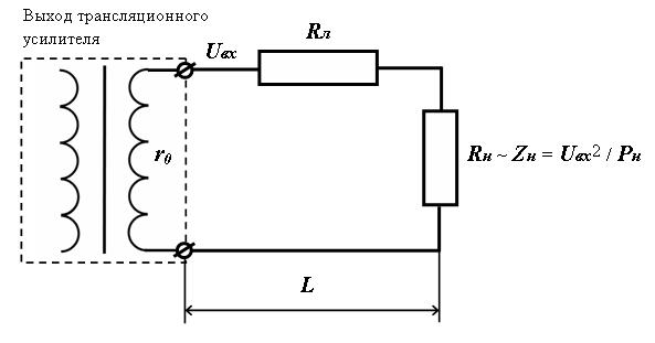
Rice. 2 - Equivalent circuit for connecting the load at the end of the line
The first stage, at which all the load is concentrated at the end of the line, will simplify the solution of the problem and go to stage 2, at which the coefficients will be determined, which will allow calculating the cross-section of the wire core in a distributed line with arbitrarily set losses.
Input data for calculation:
R n - load power in the line, W;
U in - voltage at the line input, V;
L is the total length of the line, m.
To determine the cross-section of the core of the wire S, we use empirical considerations. It is known from electroacoustics that in order to preserve the quality of the transmitted sound signal, the voltage loss in the line should not exceed 10% (this value corresponds to a power loss of about 20%, which is considered to be the norm), which for a resistive divider (see Fig. 2 ), can be written as: R l ~ 0.1 R n, where R n is the load resistance, Ohm.
Substitute this ratio into formula (3):

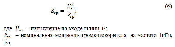
In transmission lines, the load is transformer loudspeakers. In this case, the impedance value of the loudspeaker at a certain frequency can be taken as the load resistance R n. The impedance of the transformer loudspeaker Z gr is the frequency-dependent (complex) impedance of the primary winding of the audio transformer. Most transformer loudspeaker manufacturers indicate impedance values for maximum power at 1 kHz.
The impedance of a transformer loudspeaker Z gr can be obtained from 2 well-known formulas:
- Ohm's law for a chain section: J = U / R,
- Load powers: P = JU.
When using several transformer loudspeakers connected in parallel as a load, the total impedance Z is calculated by the formula:

Formula (7), which determines the conductivity of the entire circuit, is inconvenient for calculating the total load impedance, especially for a broadcast line with a large number of loudspeakers of different power. To calculate the total impedance Z of several transformer loudspeakers, it is convenient to use formula (6), in which P gr must be replaced by the total power of all transformer loudspeakers P n, consisting of the sum of the powers of individual loudspeakers P i:
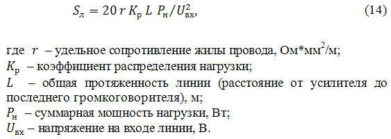
Using the total impedance of transformer loudspeakers Z (7) as the load resistance Rн and substituting (6) into (5), we obtain a useful formula that determines the cross-section of the wire core S depending on the load power Рн, the input voltage Uin and the length of the line L:
Formula (9) is valid for line losses not exceeding 10% and provided that the entire load is concentrated at the end of the line (Formula 8 is very effective for long lines (L more than 150m). On short lines (L less than 150m), one should not forget about the ratio of the cross-section and the current rate (formula 2).
5. Calculation of the cross-section of the conductive core of the wire in the distributed line
In broadcasting systems with transformer matching, the loudspeakers are connected to a common line, always in parallel and distributed along it with varying degrees of uniformity (see Fig. 3).

Rice. 3 - Equivalent distributed line circuit
In a distributed system, transformer loudspeakers (transformer loudspeakers are connected to the main line only in parallel, as a rule, through junction boxes (the resistance of which we do not take into account) they are connected to the main line with section S, through junction boxes with taps of a smaller section S i. distributed line, you can use the formula (9): S i = 20rl i P gri / U l 2, where li is the length of the i-th branch - the distance from the main line (distribution box) to the loudspeaker (m), P gri - power i -th loudspeaker, W.
The most urgent is the problem of calculating the cross-section of the main conductor of the wire, the translation line. In real distributed structures, the distances to the loudspeakers, as well as their power, vary. Such problems are solved by iterative methods using Kirchhoff's laws, they require special calculation skills or the use of software tools.
The simple and effective method proposed below can be used to solve the widest range of problems. The essence of the method is based on an obvious and simple consideration: if most of the load is concentrated not at the end, but at the beginning of the line, then the total load on the wires will decrease.
Example: For the situation shown in Fig. 4, the equivalent load power P eq = P 1 + P 2, is somewhere in the middle between the loudspeakers with powers P 1 and P 2.
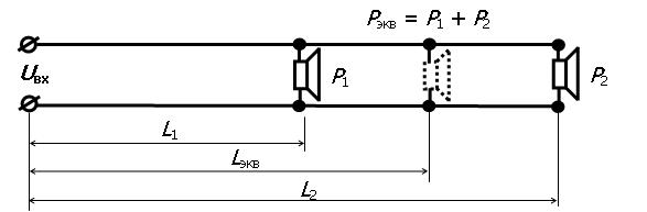
Rice. 4 - Example clarifying the meaning of the distribution coefficient
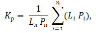
We introduce a coefficient that takes into account the unevenness of the load and is based on the already constructed formula (9, is valid for the case when the entire load is concentrated at the end of the line), from which it can be seen that the cross-section of the wire core is directly proportional to two variables: the length of the line and the load power and, therefore , the distribution coefficient should be normalized with respect to these variables. Let's give a definition:
Load sharing coefficient K p- dimensionless coefficient taking into account the distribution of the load along the line, Fig. 4:

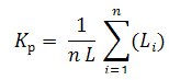
In distributed lines, in which loudspeakers of the same nominal P gr are used, the total load can be calculated as: P n = n Pgr and in this case the distribution coefficient is presented as the arithmetic mean of the distances to the loudspeakers:
In the case when the distances to the loudspeakers L i are not known, the distribution coefficient K p can be represented as the arithmetic mean between two cases when the entire load is located at the beginning of the line (L = L / n) and at the end of the line (L = L n):
The dependence of the distribution coefficient Kp (12) on the number of loudspeakers n is given in Table 1 (formula 12 is valid: so for one loudspeaker (n = 1), K p = 1, for a large number of n = 10, K p tends to 0.5) ...
Table 1
Dependence of the value of the distribution coefficient
on the number of load elements (loudspeakers)
| n | 1 | 2 | 3 | 4 | 5 | 6 | 7 | 8 | 9 | 10 |
| K p | 10,75 | 0,67 | 0,63 | 0,6 | 0,58 | 0,57 | 0,56 | 0,56 | 0,55 |
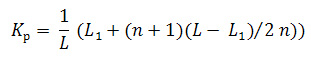
The most common case is when the entire load is distributed in a certain predetermined interval from L 1 to L, where: L is the total length of the line. In this case, the distribution coefficient can be represented as a result of averaging in the range from L 1 to L (the arithmetic mean between L 1 and (L - L 1) (n +1) / 2n (see f-lu, 12), normalized with respect to L ):
Let us check the validity of formula (13):
when L 1 tends to 0, K p tends to ((n + 1)) / 2n - formula (12);
Example: Let us calculate the value of the distribution coefficient for the case when the load (for example, 10 loudspeakers) is located in a building located at a distance of L 1 = 300 m from the amplifier. The total length of the line is L = 500m: K p = (300 + 0.55 * (500-300)) / 500 = 0.82.
It is convenient to present the distribution coefficients for different cases in the form of a table:
table 2
Distribution coefficients K p for different cases
| Formulas for calculating K p | Application condition |
|---|---|
 |
This formula is used if the powers and distances to the load elements are known. |
 |
This formula is used if the powers of the load elements are equal and the distances to the load are known. |
 |
This formula is used if the distance to the first loudspeaker and the total length of the line are known, the powers of the load elements are not known. |
| This formula is used if the power and distances to the load elements are not known. |
We introduce the distribution coefficient K p, Table (2), into the formula (9):
6. Calculation of line losses
Long lines have a sufficiently large intrinsic resistance, which leads to the dissipation (loss) of some of the power on them. This fact cannot be ignored. In practice, the voltage losses are initially calculated, and already from them they pass to the power losses.
Voltage losses - the ratio of the voltage on the line Uл to the total voltage at the input of the line U in:
According to Kirchhoff's law, the ratio of the resistances is proportional to the ratio of the voltages falling on them, therefore, it is more convenient to express the voltage losses P n through the previously obtained line resistance R l and the load resistance R n:
Determine the amount of voltage loss for the distributed line. Since the distribution coefficient K p (Table 2) demonstrates a word decrease in the length of the line, and, consequently, its resistance R l, then the losses in such a line should accordingly decrease.
Let us supplement formula (15) with the distribution coefficient K p, Table (2):
In practice, not only voltage losses are calculated, but also power losses.
Power losses - the ratio of the power allocated on the line P l to the total applied power: the sum of the power allocated on the line and at the load P n.
It is convenient to calculate power losses through voltage losses (16), for which it is sufficient to take into account that the load power is directly proportional to the square of the load voltage (see formula 6):
Example: From (18) it can be seen that when voltage losses are more than 25% (The value of 25% according to the existing standards is the maximum permissible), power losses (P m = (1 - ((100-25) / 100) 2) * 100 = 44%) are approaching 50% (the power is reduced by 2 times (a decrease in power by 2 times (corresponds to a decrease in sound pressure by 3dB), which is noticeable for the listener)), therefore, the value of voltage losses P n> 25% will be considered critical.
7. Calculation of the cross-section of the wire core, taking into account the losses in the line
Let's go back to calculating the cross-section of the wire core. Let's calculate the cross-section of the conductor of the distributed line taking into account voltage losses. Recall that formula (9) is based on the assumption that voltage losses in the line should not exceed 10%, which made it possible to use the ratio: R l / R n = 0.1. With a loss value other than 10%, this ratio will change. Let's build a coefficient that allows us to take into account any expected losses in the line, as K p = R n / R l.
It is convenient to relate this coefficient to voltage losses and interpret it as expected losses. Using formula (15) we get:
Let's check the validity of this formula: When P n "tends to" 100%, K p "tends to" 0, R n "tends to" 0 - all voltage remains on the line. When P n "tends to" 50%, K p "tends to" 1, R l = R n - the voltage on the line and the load is the same. When P n "tends to" 10%, K p "tends to" 9, R l = 0.11 R n - the voltage on the line is about 10 times less than at the load. When P n "tends to" 0%, K p "tends to" ∞, R l tends to 0 - the voltage on the line tends to 0.
Let us supplement this coefficient with formula (14):

Calculation example
Let's calculate the sound pressure of the loudspeaker, taking into account the losses on the wires.
Loudspeaker sound pressure: P dB = SPL + 10 lg (P gr), where: SPL - loudspeaker sensitivity, dB, P gr - loudspeaker power, W.
It is convenient to introduce power losses into this formula (formula 18) and interpret given f-lu as: Sound pressure level, calculated taking into account power losses: P dB = SPL 10 lg (P gr (100-P m) / 100), where P m - power loss,%.
8. Calculation algorithms
Algorithm No. 1 "Calculation of the conductor cross-section for a uniformly distributed load"
- Let's calculate the loss factor, formula (19).
- Let's calculate the resistivity for copper, taking into account the temperature, formula (4).
- Substitute the obtained values into formula (20).
Algorithm No. 1 "Calculation of voltage losses in an existing line
- Let's calculate the resistance of the wire core, taking into account the temperature, formulas (4), (5).
- Let's calculate the total load in the line, formula (8).
- Let's calculate the load resistance, formula (6).
- Let's calculate the distribution coefficient, Table (2).
- Let's calculate the voltage loss, formula (16).
9. Calculation example
Let's calculate the required cross-section of the wire core for various lengths and loads in the line, for which we use the capabilities of the Microsoft Excel program, Fig. 5.
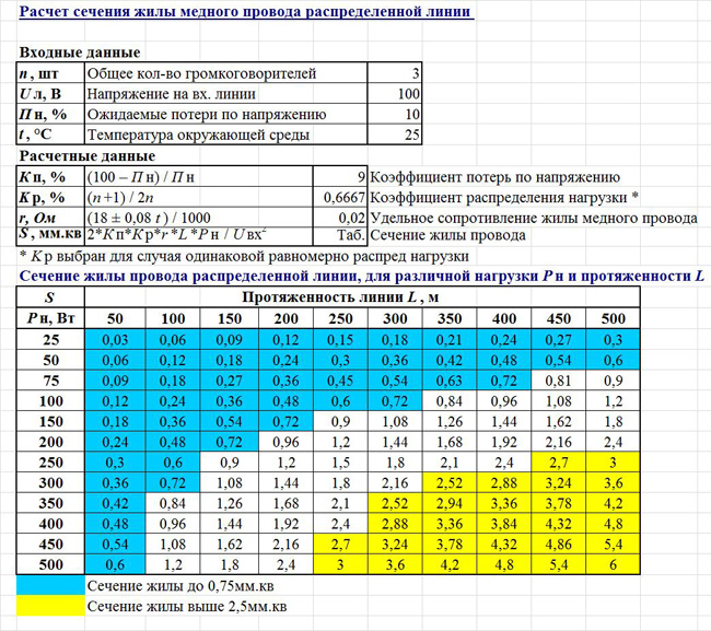
Rice. 5 - Calculation of the cross-section of the conductive core of the wire of the distributed line
Based on the described algorithm, a